Loading ....


SRS 3 panels offer architects advantages that give their designs more freedom and flexibility. The panels are non-directional, which enables them to be installed left to right, right to left, or from the middle of the roof in both directions.
SRS roofing panels provide clean, sleek sight lines and maximum weather protection.
SUBSTRATES
• G90 Galvanized base material, optional Galvalume®†
GAGES
• 91mm, .76mm and .60mm
• Optional 1.2mm gage available with .91mm gage battens
PANEL WIDTH
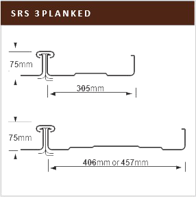
• 305mm 406mm and 457mm panel widths available; field-formed continuous lengths up to 67.1m
PANEL LENGTH
• Factory formed panel lengths to 13.7m
PANEL HEIGHT
• 51mm nominal seam height
SLOPE
• Minimum slope 4.2% without endlaps, 8.3% with endlaps
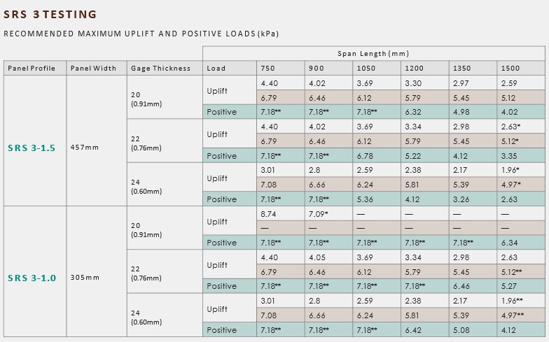
All tabulated loads are based on triple span configurations.
* Tested in accordance with COE Guidespec and ASTM 1592. These recommended loads are based on a safety factor of 1.65 at ultimate failure load or 1.3 of yield failure, whichever is lower. No increase in allowable stress due to wind permitted.
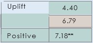 This value represents the recommended maximum uplift load.
This value represents the higher recommended maximum load achieved through the use of deflection limiters.
This value represents the recommended maximum positive load. Dead load is based on the weight of the panel. Deflections are not to be greater than 1/180 of the span length.